Each aircraft moving in the atmosphere has six degrees of freedom; it is in fact free to translate along three mutually perpendicular axes and to rotate around them. Consequently, its motion during flight will be determined by the forces and moments acting on it. The measurements of forces and moments on aircraft are normally performed in the wind tunnel (by means of scale models) and have the purpose of estimating the aerodynamic load acting on the aircraft in flight, both to verify its structural integrity and to analyze its performance.
It is very useful to measure the forces and moments acting on the model or on parts of it by means of a dynamometric balance because it allows their direct measurement without having to determine the pressure distribution on the body under examination.
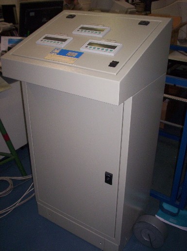
The balance supplied by the laboratory is an external lateral balance (that is, it is positioned outside the wind tunnel so as not to influence the fluid vein and to allow the support of the profile in the test chamber by means of an arm) electronic three-component, model AF6109n of the STEM-ISI Impianti Spa, combined with HBM’s MVD2555 measuring amplifier. It has a measuring shaft on which four HBM UStype 6 / 350DK11E strain gauges are mounted, connected to a Wheatstone bridge and whose signal is processed by the measuring amplifier which directly provides the indication in N of the force measured by means of three indicators.
The measurement ranges allowed by the scale are the following:

Lift -500 ÷ +500 N
Resistance 0 ÷ +100 N
Moment -30 ÷ +30 Nm
It is possible to connect an acquisition system to sample the temporal evolution of the loads.
Following the application of a force on the balance shaft, an effort is generated on it that tends to deform it. Once this deformation is known, it is possible to trace the force applied by means of the four strain gauges connected to a bridge. Resistance electrical strain gauges are sensors used to detect the physical deformations of a body subjected to mechanical stress; they consist of a grid of very thin metal wire (usually constantan) rigidly applied to a support of plastic material. They are used by gluing them to the surface of the body whose deformations are to be measured (in this specific case the shaft); The strain gauge wire follows the deformations of the surface to which it is glued, elongating and shortening together with it; these dimensional variations cause a variation in the electrical resistance of the wire, so that, by measuring these variations through suitable circuits, it is possible to trace the extent of the deformation that caused them.
The device that allows the measurement of this resistance variation is the Wheatstone bridge, an analog zero instrument. Known deformation and variation of resistance, it is thus possible to ascertain the applied force, whose value, suitably amplified, is shown on the display.