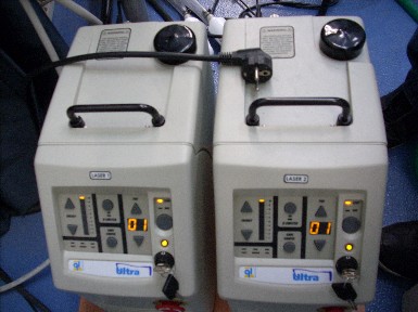
The LASER system supplied by the laboratory is an ULTRA CFR Nd: YAG, configured to come out with a wavelength range of 532 nm (wavelength corresponding to the green color).

The energy is regulated by selecting the voltage of the Flashlamp and the delay to be assumed in the opening of the Q-Switch. The maximum energy of the beam is 50 mJ and is obtainable with a 135μs delay between the ignition of the Flashlamp and the opening of the Q-Switch. It is possible to decrease the energy content by increasing the delay time up to 375μs.
The system in use consists of two Nd: YAG LASER to meet the need for two pulses spaced only a few hundred microseconds with the maximum energy content attainable for the PIV measurements for which the system is intended.
The actual management of the various components takes place through the synchronizer (TSI model 610034 Laser Pulse Synchronizer) which can be controlled from the INSIGHT interface.
The various triggers (impulses) that activate all the other instruments start from this device.
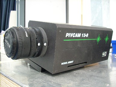
The power supply takes place directly from the electrical network and, through this device, the camera is also powered (PCO 1Mpx).
The camera is also connected, via optical fiber, to the PCI Image Grabber card: all information relating to the images passes through this connection.
The card has an additional input dedicated to the BNC cable for the transmission of the trigger for the acquisition chamber: the other end of the cable is connected to the CAMERA TRIGGER port of the synchronizer. Another cable connects this to the PC: the serial cable for transmitting data in memory.
The last devices controlled by the synchronizer are the two LASERS, connected to the two pairs of FLASHLAMP and Q-SWITCH ports again by means of BNC cables.
Through INSIGHT it is possible to manage all these connections in order to acquire the two images corresponding to the two light pulses of the LASER. In addition, it is possible to choose the power and the time interval that separates them from the latter, since the LASER time sequence has already been set in the software.
Once all the connections between the various devices have been made, it is necessary to create the desired laser blade and position the camera in order to acquire the image of the illuminated plane.
The light blade is obtained by using a cylindrical lens positioned directly at the LASER outlet, for example, a horizontal laser blade is created that perfectly cuts the cone of a spray along the center plane.
The following figure shows a schematic representation that shows how images can also be obtained by using the LASER and a digital camera.